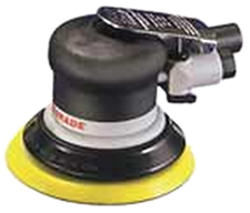
Dynabrade Random Orbit Sander
Product Review and Rebuild Guide
By Rick Christopherson
Preface: This is one of the very first articles I ever
wrote, and it actually predates the existence of my website. Since the
time this article was written, I have bought several Dynabrade sanders
of varying vintages. After over a decade of hard use and even abuse, I
finally decided to rebuild the original sander that I owned when this
article was first written. As a testament to the ruggedness and durability of these sanders, with a simple rebuild kit and about 1-hour's labor, I rejuvenated my oldest, most abused sander to factory fresh condition. I got a complete rebuild kit from PhillyTools and at the end of this review, I will explain how easy it is to rebuild a Dynabrade sander.
![]()
This article is also available in a printer-friendly PDF file. Click Here.
Review
 Most woodworkers consider sanding a project to be the most arduous and
difficult task within woodworking. Even with a random orbit sander,
it is time consuming and frequently fraught with undesirable results.
Two of the greatest complaints I hear from fellow woodworkers are that
their sanders leave swirl marks, and that their hands go numb from the
vibration. Well, these are problems that plague even the best electric
sander, but are virtually nonexistent with a Dynabrade pneumatic sander.
Most woodworkers consider sanding a project to be the most arduous and
difficult task within woodworking. Even with a random orbit sander,
it is time consuming and frequently fraught with undesirable results.
Two of the greatest complaints I hear from fellow woodworkers are that
their sanders leave swirl marks, and that their hands go numb from the
vibration. Well, these are problems that plague even the best electric
sander, but are virtually nonexistent with a Dynabrade pneumatic sander.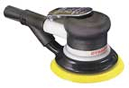 I
have found the Dynabrade sander to provide virtually swirl-free sanding
at even fairly coarse grits, like 120 grit, and completely swirl-free
sanding with no higher than 180 grit. Furthermore, the sander has a
much longer life-span than the electric types, and produces less
operator fatigue due to less vibration.
I
have found the Dynabrade sander to provide virtually swirl-free sanding
at even fairly coarse grits, like 120 grit, and completely swirl-free
sanding with no higher than 180 grit. Furthermore, the sander has a
much longer life-span than the electric types, and produces less
operator fatigue due to less vibration.What is "Dual Action"
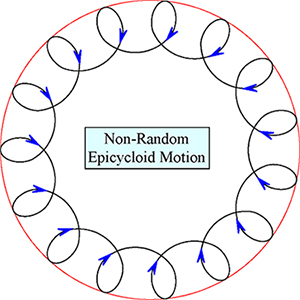 Random orbit sanders are frequently referred to as Dual Action sanders.
This is because each point on the sanding pad moves in two interrelated
circular paths. This basic motion is similar to the old SpiroGraph toy,
and this is called an epicycloid. It is the result of rotating one
circle about another, hence the term Dual Action. However, a true
epicycloid is not random motion. Gear-driven sanders operate on this
motion, and they are very aggressive, but they leave a lot of swirl
marks behind.
Random orbit sanders are frequently referred to as Dual Action sanders.
This is because each point on the sanding pad moves in two interrelated
circular paths. This basic motion is similar to the old SpiroGraph toy,
and this is called an epicycloid. It is the result of rotating one
circle about another, hence the term Dual Action. However, a true
epicycloid is not random motion. Gear-driven sanders operate on this
motion, and they are very aggressive, but they leave a lot of swirl
marks behind.What is "Random Orbit"
To achieve random motion, the sanding pad is allowed to rotate freely. It is this free motion that reduces swirl marks because the marks are more random than the circular pattern that the human eye can quickly discern. If viewed under a microscope, the loops shown toward the outside of the drawing above are tighter, and closer to being straight lines.What is "Orbit Diameter"
The orbit diameter of a sander is how far from the centerline that the pad rotates. This is also called the "eccentric" of the sander. There are many orbit diameters, but the two most common are 3/32-inch and 3/16-inch. Generally speaking, smaller orbit diameters result in smoother finishes, but less aggressive cutting; while larger orbit diameters result in more aggressive sanding with less smooth results.Reducing Scratches and Swirls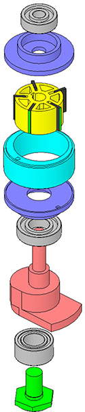
The design of a sander goes a long way toward reducing the sanding
marks it leaves behind. Some sanders leave more scratches because they
are designed to be more aggressive, and this can be good, but other
sanders leave more scratches simply because they don't provide smooth
action in their components. The best of sanders will be both aggressive
in their material removal, yet still provide a smooth finish.The more random the pattern, the less noticeable the scratches will be. As a result, anything that hinders the random motion of the pad's rotation will increase the amount of visible scratches. For this reason, you'll never find a "pad brake" on a pneumatic sander. Not only are they not needed, but they reduce the randomness of the sanding pad motion, and therefore, increase the swirl marks. If your sander pad is not visibly spinning (free-wheeling) while you are sanding, then you are not getting the full dual-action from the sander!
Electric Versus Pneumatic
The primary reason why a good quality pneumatic sander will outperform its electric sander counterpart is the quality of the drivetrain. The majority of the cost associated with manufacturing an electric sander is in the motor itself, such as the copper and laminated rotor, with less money left over for the drivetrain. A pneumatic sander has a very simple motor, and therefore, more of the cost of the sander can be associated with the drivetrain components.For example, a typical electric sander has an aluminum eccentric flywheel and a simple 1/4-inch bearing between the flywheel and the sanding pad, and all of this is held together with a single screw. On the other hand, the Dynabrade sander has a machined steel flywheel (balancer) that is actually contiguous with the rotor shaft of the motor (this is the red-colored piece in the drawing to the right). Because this eccentric shaft is a single piece with the motor shaft, there is virtually no chance for runout or wobble in the output of the sander pad.
Additionally, instead of a 1/4-inch thick bearing pressed into an aluminum bore, the Dynabrade sander uses a 5/8-inch thick bearing pressed into the machined steel bore of the eccentric balancer. The result is a dead-straight drivetrain.
Size Matters
The Dynabrade is small--Really small! At only 3 5/8 inches tall, it is almost half the size of most electric sanders, yet has more horsepower. At 1/4 hp, only a couple of the larger, heavier sanders can compare. The reason why it is small with a lot of power, is because of the pneumatic motor versus the heavy electric. Your 300 pound compressor sitting in the corner is providing the power "remotely".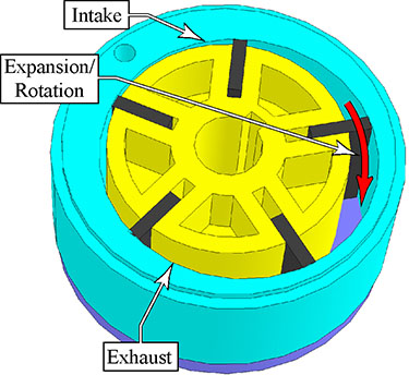
A rotary vane motor is kind of like the Wankel rotary engine made most famous in the Mazda RX7 sports car. Even though the engine types are slightly different, the primary concept is an expanding cylinder space as the rotor turns. Air enters the chamber where the rotor is closest to the cylinder wall, and pushes against the vanes as it tries to expand. On the exhaust side of the cylinder, the decreasing size of the chamber pushes the compressed gas out of the cylinder.
Fatigue
It doesn't take very long while sanding for your whole body to wear down and grow fatigued. It isn't just a simple matter of how hard you are working, but also the strain you are putting on your whole body while you sand. Part of this is exertion, but a significant portion is due to vibration and comfort. Because the Dynabrade sander is lighter than other sanders, the vibration is greatly reduced as the eccentric balancer rotates.Moreover, because the sander is not as tall as an electric sander, it takes less energy to control the sander. If you are male, you probably haven't spent much time walking around in high-heel shoes, but your wife could certainly attest that it is far easier walking around in flat tennis shoes than it is in high heels. Likewise, with your hands closer to the workpiece, it takes less effort to maintain control of the sander.
Putting Your Money Where Your Scratches Are
A few years ago when I was a magazine editor doing product reviews, I performed a scientific comparison of sander performance based on both sanding aggressiveness and the quality of the final finish. I built a motorized sanding rig that simulated the operator's movement of the sander across a test piece of maple. I weighed each test piece before and after the testing to determine how aggressive the sander operated. I also used a dissecting microscope to analyze and count the number of scratches each sander left behind. (I used to be a certified microscopist for counting asbestos fibers, and utilized the same statistical techniques for evaluating the sander scratch patterns.)What some woodworkers might find surprising is that some of the best known and popular sanders on the market actually scored the lowest in terms of both their aggressiveness and their scratch quality. As a matter of fact, contrary to reason, some of the sanders that had the worst scratch pattern also had the lowest sanding rate. But by a wide margin, the Dynabrade sander scored highest in both aggressiveness and lowest scratch count. This means it takes less time for you sand a project, and less chance that you will discover sanding swirls when you begin to apply your finish!
Conclusions
A pneumatic sander is not for everybody, but as a woodworker grows his skills and repository of tools, stepping up from an electric sander to a pneumatic sander will be one of the most significant leaps he can make moving forward. When you are ready to make this leap, don't make the common mistake of buying a cheap hardware store class pneumatic sander and expect it to perform at the level you demand. The Dynabrade sander is considered to be the best sander on the market by most professionals, and can be found in many professional shops that run the full range from woodworking to automotive body work. Once you try a pneumatic sander, you will wonder how you ever got by without one in the past.|
Sidebar: Are Pad Brakes Really Any Good? As a supplement to my analysis of sander scratch patterns several years ago, I wanted to verify my assumptions that non-randomness in the pad rotation increased the scratch pattern of the sander. I took several electric sanders that had pad brakes and repeated my testing with the pad brakes removed or disabled. The results were absolutely conclusive without exception. Every single electric sander performed better when the pad brake was removed. Moreover, the Porter Cable sander has, without doubt, the most effective pad brake of any electric sander I examined. As a result, it also had the most dramatic improvement of scratch patterns when the brake (a plastic o-ring) was removed. |
The results listed below are in scratches per square inch (s/in2): | |
| Porter Cable332 | ||
| w/brake: | 2693 s/in2 | |
| w/o brake: | 537 s/in2 | |
| DeWalt 421 | ||
| w/brake: | 1571s/in2 | |
| w/o brake: | 500 s/in2 | |
| Festo ET2E | ||
| w/brake: | 713 s/in2 | |
| w/o brake: | 486 s/in2 | |
| Metabo XSE 425 | ||
| w/brake: | 181 s/in2 | |
| w/o brake: | 65 s/in2 | |
|
Makita BO5010
(pad appeared to be slightly bent) |
||
| w/brake: | 503 s/in2 | |
| w/o brake: | 741 s/in2 | |
 One
of the main reasons for updating this article is because I recently
rebuilt one of my oldest sanders, and I wanted to relate this
experience to others. For most sanders, when they reach their end of
life, they are done and just scrap. With the Dynabrade, the design is
so robust that the sander can be rebuilt and brought back to new
condition indefinitely.
One
of the main reasons for updating this article is because I recently
rebuilt one of my oldest sanders, and I wanted to relate this
experience to others. For most sanders, when they reach their end of
life, they are done and just scrap. With the Dynabrade, the design is
so robust that the sander can be rebuilt and brought back to new
condition indefinitely.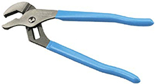
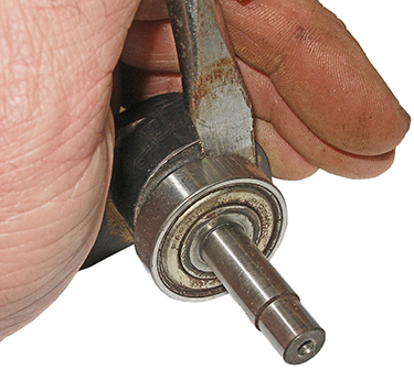
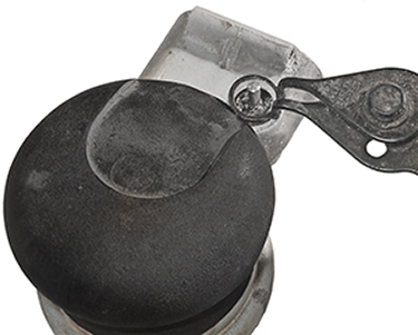
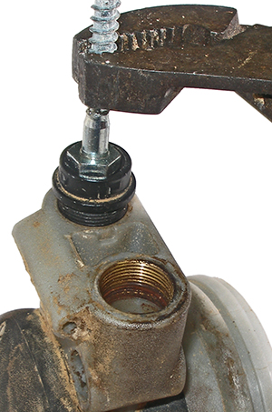
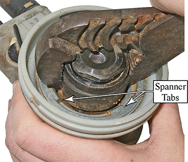 The most complicated part of disassembling the sander is removing the
spanner nut holding the motor into the housing. I found that a standard
Arc Joint pliers (shown to the left) works very well for removing the spanner
nut. I open the pliers so that the outside of the jaws are engaging two
of the four tabs on the inside of the spanner nut, and then I just
unscrew the nut (counterclockwise).
The most complicated part of disassembling the sander is removing the
spanner nut holding the motor into the housing. I found that a standard
Arc Joint pliers (shown to the left) works very well for removing the spanner
nut. I open the pliers so that the outside of the jaws are engaging two
of the four tabs on the inside of the spanner nut, and then I just
unscrew the nut (counterclockwise). 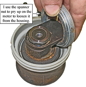
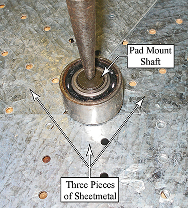
 Disassembling the Motor
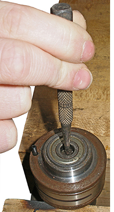
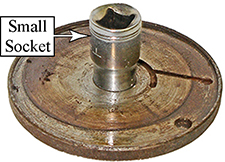 Turn
the upper cylinder cap over, and drive the upper bearing out of the cap
in a similar fashion. I found that a small socket would fit through the
cylinder cap, but not the bearing, so this worked well for driving the
bearing out of the cap (see image to the right).
Turn
the upper cylinder cap over, and drive the upper bearing out of the cap
in a similar fashion. I found that a small socket would fit through the
cylinder cap, but not the bearing, so this worked well for driving the
bearing out of the cap (see image to the right).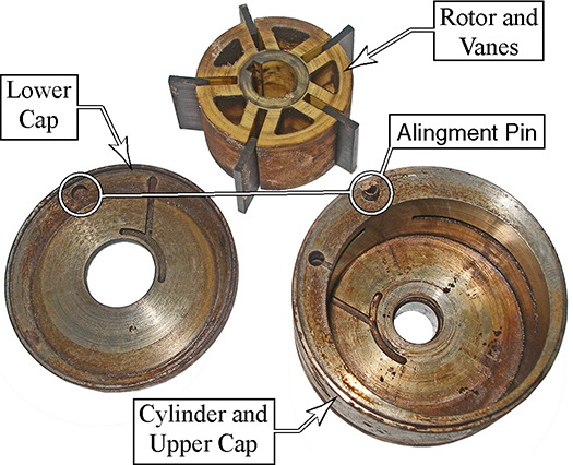
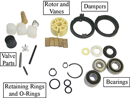
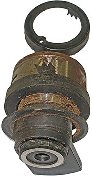
 Just
like an automobile engine, the less restriction you have in getting the
air into and out of the motor, the more efficient and powerful it will
operate. The inlet contains a valve, and the exhaust contains a brass
filter and silencer pads.
Just
like an automobile engine, the less restriction you have in getting the
air into and out of the motor, the more efficient and powerful it will
operate. The inlet contains a valve, and the exhaust contains a brass
filter and silencer pads.