 One of
the more complex projects I designed and built was a round diningroom
table. My client came to me with the request for a 5 1/2 foot round
dining table which would expand to 7 1/2 feet yet remain
(predominately) round.
 One of
the more complex projects I designed and built was a round diningroom
table. My client came to me with the request for a 5 1/2 foot round
dining table which would expand to 7 1/2 feet yet remain
(predominately) round.
I will start out with a quick overview. And for those interested, at the bottom of this discussion, I will include some of the specific details about the actual construction, including the lessons learned in the process (Nah, I never make mistakes!)
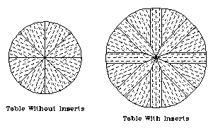
The drawing above shows the original CADD drawings created for the proposal. The African Ribbon Striped Mahogany was oriented radially to the circle.
The table has 8 pie-shaped primary-leaves, and 8 arrow-shaped insertion-leaves. To make the table convenient to use, a hand crank (like on an old model T) is concealed in the pedestal. Turning the hand crank operates a right-angle wormdrive (20:1 ratio) which spins a spreader disk under the primary-leaves. As this spreader disk rotates, all 8 leaves flay outward together. The insertion-leaves are added to the table, and the wedge-leaves are drawn back in to tighten the circle.
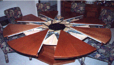
 The
next picture shows the table fully opened, but before the leaves have
been added. The black octagon in the center is the spreader disk, and
is connected to each of the wedge-leaves with connecting arms. At the
bottom right side of the photo, you might be able to make out the
hand crank which operates a right angle wormdrive. When not in use,
the crank fits inside the pedestal, and out of view. The slides are
250 pound capacity Grant (brand) slides, two per wedge.
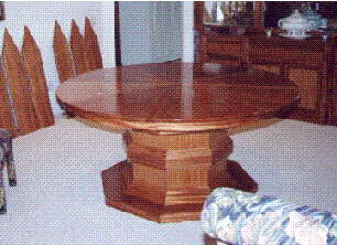
 In
the next photo, the table is shown in its medium position (2 inch
wide leaves were added as an afterthought for aesthetic reasons.)
Against the wall, you can see some of the arrow-shaped insertion leaves. The octagon pedestal is rather large and heavy to stabilize the table in its open position.
It took about two weeks of actual woodworking, but I spent almost as much time designing the mechanical layout, waiting for metal fabrication, and final adjusting.
(The buffet cabinet in the background is also one of my projects. This was a new home construction which was large enough that I broke it up into 8 phases of work)
After the wedges were cut, I ran them through the widebelt sander, which brought them down to 15/16 or 7/8 inch thickness (not sure anymore)
The following was a mistake I made: I next custom fit the 8 wedges by edge sanding them on a Powermatic model 13 edge sander. This compensated for the minor variations from 22 1/2 degrees of the original saw cuts, plus straightened the edges. I sanded each edge until it fit tightly to the next, and there was no net-gap in the whole circle. When I went to add the arrow-leaves, I realized my error. Each of the wedge leaves must be precisely cut, and be exactly the same. By custom fitting each of the wedges to one another, I realized that the arrows needed to be custom fit too, but there was no guarantee that the leaves would always be in the same position.
So I brought all 8 wedges back to the table saw for re-cutting. I used an Excalibur SLT60 sliding table, set at 22 1/2 degrees. (Two cuts result in a wedge with a 45 degree point). I cut the first 4 wedges, and test fit them using a straight edge along the semi-circle's diameter. After some fine tuning of the sliding table's angle, I was moderately confident that I had 22.50 degrees. So I continued to cut all of the wedges. After more test fitting, and fine tuning, I had the sliding table dialed in to 22.500 degrees.
Knowing that my cross-cut fence was precisely set at 22.500 degrees, I decided to re-cut all of the arrow-leaves too. The setup used also ensured that the point of the arrow was perfectly centered. (I don't remember what this jig was like, but the process requires that the arrows be flipped over and cut twice.)
By this time, I had already discovered that the wedges were fluctuating with minor moisture content change. So as soon as they came off the saw, they were sprayed with both sanding sealer, and the first two coats of top-coat lacquer to keep them moderately stable. (I won't use solid lumber for this type of project again.)
I placed the 8 wedges tightly together without gaps, and screwed several scraps of wood to the underside to hold them in place. I rigged up a plywood base for the router to cut a 5 1/2 foot circle. This was the second mistake. Since the router was primarily cutting cross-grained at all times, I had horrendous tearout, especially at the corners between wedges.
So I moved this whole assembly to the table saw. Under the assembly, I had a board long enough to clamp to the table saw's extension table, and screwed into the scrap wood under neath. This made a pivot point so I could rotate the assembly across the blade. (The extension table of my saw is 6 feet wide and 8 feet long.) With the saw running, I raised the blade, and spun the table (several passes). This resulted in a perfectly round disk, with absolutely no tearout, and surprisingly clean edges.
The next step was the skirt boards. I again used the router base from before, but reduced its radius by a few inches, and cut a 3/8 inch deep by 1/2 inch wide dado around the circumference of the leaves. I took 8 pieces of 1/2 inch by 3 inch solid mahogany, and cut 1/8 inch saw kerfs spaced 1/2 inch apart, and 3/8 inches deep. To bend these into the dados, I wetted the outside surface, let it stand a while, rewetted, and placed them into the dado. I was careful not to get the gluing surface wet though. These were then clamped until dry. The same was done for the arrows.
I used ultra-heavy-duty drawer slides (250 pound cap.) to secure the wedges to the table's substrate. While these move quite nicely, if I ever build another table like this, I will have the entire undercarriage custom built as a single unit with micro-adjustment screws for aligning the parts. It was only after many hours of lost work that I realized none of this tuning could be done until the table platform was completely mounted onto its pedestal. Yet once on the pedestal, I couldn't access the adjustments. (I had to make access holes under the substrate, and prop the whole assembly up such that it was still perfectly flat.)
The pedestal was made from 8 pieces of MDF core plywood and biscuits for alignment of the miters. Custom made mouldings gave it its shape.
I spent more time designing the spreader mechanics than I did cutting the wood. This was just CADD work, tolerances, and engineering, so I won't go into it. I did learn, as the table was leaving the shop, that the spreader disk's shaft experiences over 1,000 pounds of force during its operation. I had to make a couple of last minute re-designs to account for this much force. (The last change was after the table was delivered and setup, but luckily before the client returned home. The wormgear literally pushed itself (screwed itself) right out of its own chassis due to the forces. I had to rush out and have a cover plate made to stop this from happening. The gearbox was designed to have this plate in place, but it didn't automatically have one.)
Most of my projects challenge my creativity, but this one was a full engineering challenge. {man} I loved doing it.
