| The substrate is where all
other
components come together for the whole upper section of the table.
Because of
the critical nature of this component, it is a steel-frame reinforced
sheet of 1-inch Appleply. Since the substrate is nearly 6 feet in
diameter, it needs to be glued up from standard sheets. The strength of
the two joints is paramount. |
 |
Jointing the Edges
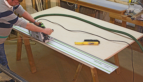
I've heard that many woodworkers consider a factory edge to be usable
as-is, or that it is used as a reference for square. I consider a
factory edge neither square, nor usable. However, at 130 pounds a
sheet, this is not something I want to drag onto the tablesaw, and at
that weight, I still wouldn't be assured a clean cut. |
 |
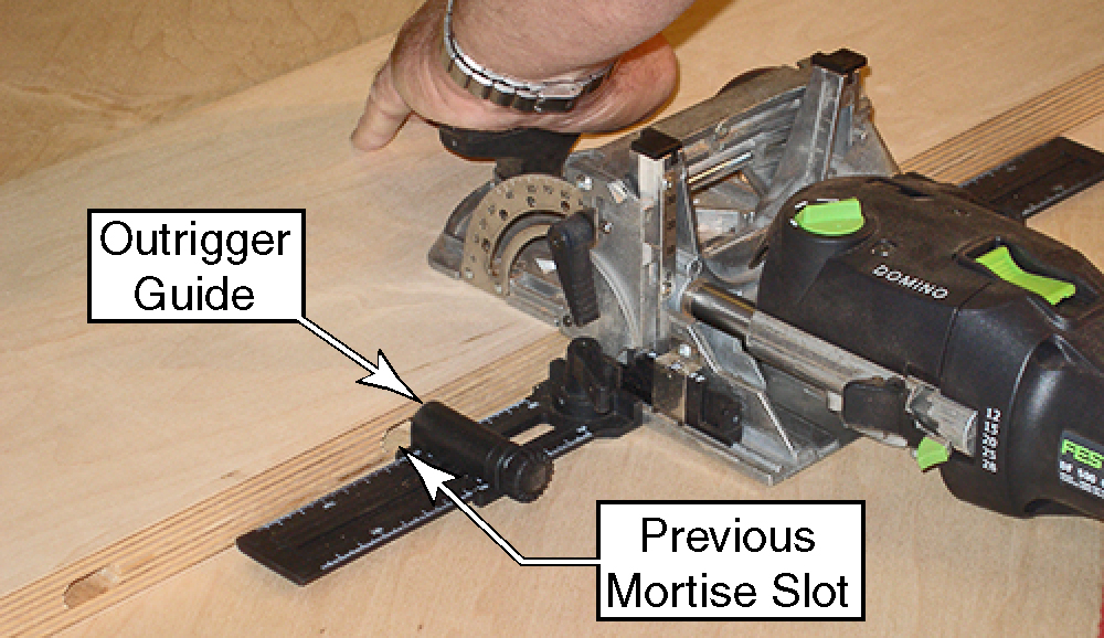
| For strong joints, I used the
largest size Domino tenon: 10mm x 50mm. This is important because
edge-joining laminated plywood is not necessarily a strong joint
because half of the laminates are edge-grain and the other half are
end-grain. The tenons will make this a very strong joint. I also decided to try the optional outrigger guides. These worked pretty well considering I didn't follow my own instructions that I wrote in the Owner's Manual. You are supposed to expand the mortise slot when you use the outrigger guides (that's what the little green dial on the top of the joiner is for). However, I decided that I wanted to keep the mortises tight side-to-side, so I plunged them at the standard setting. Surprisingly, only the last two mortises on just one side were off by about 1mm (1/16"), which was easy to tweak. .Obviously I could have followed the
instructions and widened the slots, but I wanted to see how well it
would work without. |
 |
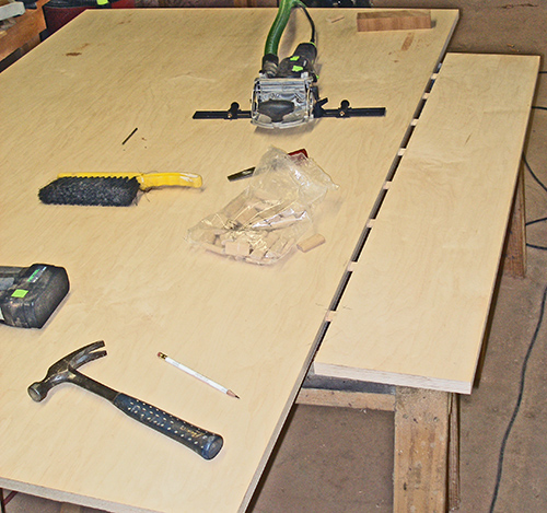
Test FittingBecause the tenons are so tight and precise fitting, I have made it a habit to test fit my tenons to make sure I haven't made any mistakes in their placement. What you might be surprised to learn is that when I spun the board around to mortise the other side, I left this board hanging unsupported over the sawhorses. Even without full penetration, the tenons are strong enough and tight enough to support the board without sagging even with that big gap in between. |
 |
Cutting the CircleThis might be hard to believe, but I would have actually preferred to cut the circle out on the tablesaw. I thought about it for a while, and I just didn't like the notion of lifting this sheet over to the saw and rigging up a trammel point underneath it. I did this when I cut the wedges out on the original table because the router was tearing out at the joints between wedges, and I got an incredible cut with the tablesaw.Instead, I decided to use the standard approach of using the router with a trammel. After looking around the shop for an appropriate sized scrap to make the trammel, I saw this piece hanging on the wall in an unused corner of the shop. After taking it down from the wall, I realized it was the original trammel from the first table, and I hadn't used it since then. That's when I recalled that I had used a router to cut the original substrate, and it was only the tabletop that I cut with the tablesaw. |
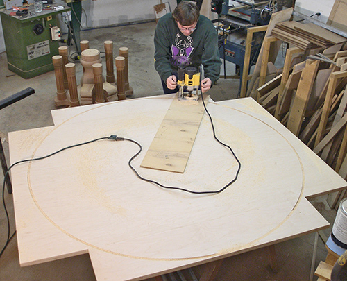 |
| I wasn't sure which router bit I
wanted to use. I have a 3-wing
straight bit, but it only has a 1/4" shank. My 1/2" bits get so much
use that I knew none of them were sharp enough. I would have loved to
use my 1-1/2" pattern bit, but I would have had to pre-cut the circle
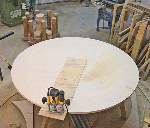
with a jigsaw. Then I remembered that Carlo Venditto (the CEO of the former Jesada Tools) had given me a down-spiral, solid carbide bit for a magazine article I wrote years ago. The large and aggressive bit had catastrophic results on the small workpiece for the article, so I ended up never using it. However, on a large cut such as this, the aggressiveness coupled with the down-spiral would be perfect, and it was. Even though the bit could have handled the job in a single pass, I still made several passes to complete the cut. I removed the router from the trammel, but left the trammel on the substrate for drawing layout lines. |
 |
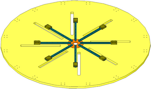
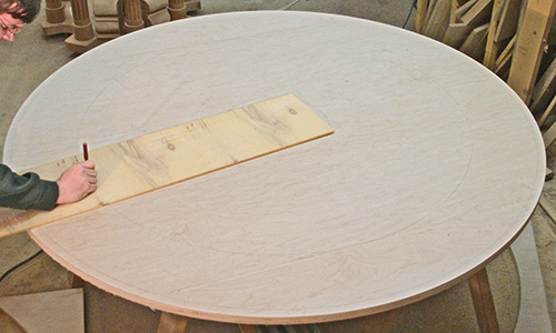
Drawing the Layout LinesWhile I had the trammel installed on the table, I wanted to start drawing the layout lines that I will need later to locate components and cutouts. They are hard to see here, but there are three primary layout circles drawn. The outer circle locates one screw hole in each of the 16 linear slide pillow blocks (these screw holes are visible in the first drawing above). The other two lines block out the 8 radial cutouts, which are also visible in the above drawing. |
 |
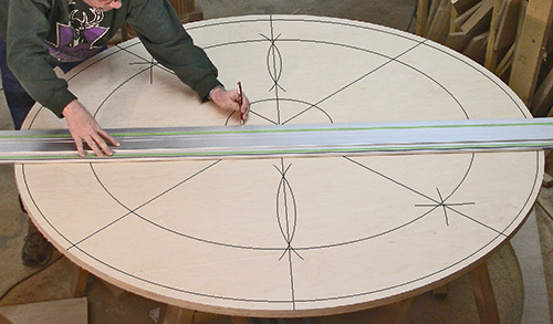
Dividing the Circle into 45º Sectors
The precision of the 45º lines on the substrate are the most
critical of the project because this will be used to lay out the linear
slides later on. This isn't something that could be trusted to simple
measuring tools. Instead I used drafting techniques to lay out precise
angles. |
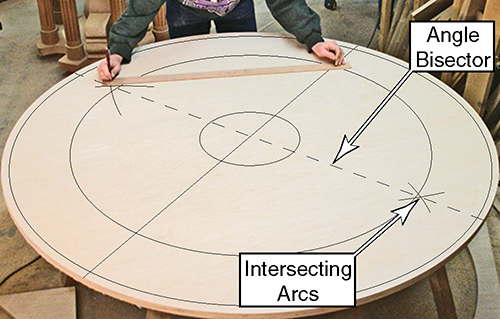 |
| The final step is drawing the two
lines that bisect the two 90º lines. The concept is the same,
except I used a smaller radius arc. I also swung the arcs enough to
create two intersections per pair. This means that the bisecting line
has to pass through four intersections plus the center of the circle.
If it didn't pass through all of these points, then it would have told
me that I made a mistake somewhere along the way. Because of the mathematical nature of this method, I can be assured that the lines are accurately drawn with a precision probably down to a thousandth of a degree. That might seem like I am being anal retentive, but this is one of the hardest lessons I learned from building the first table. Every error I make in laying out the position or shape of the components cascades down the line to other components later. I'll explain this topic more when I cut the pie-shaped wedges. Up Next: The pie-shaped wedges. |
 |
| <<PREVIOUS NEXT>> |
 |