|
I knew it would be quite some time before my machine shop could get any of the mechanical components ready for me, and without them, I couldn't begin working on the upper section of the table. So I decided to work on the pedestal first. This is the opposite approach I took 10 years ago, but back then, I didn't design the pedestal until after the whole upper table was finished. This time around, the entire table was fully designed and documented before I even ordered a single component. Center Column Glue-up
|
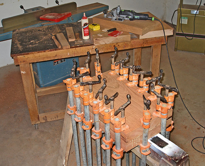 |
After the first two glue ups (shown above) were completed, I
cut them to width and length. However, before cutting them to length, I
re-squared the sliding table on the tablesaw to ensure that the cuts
were true. I realized early on that I would not be able to square the
ends of the final glue up due to its size, so this was the last chance
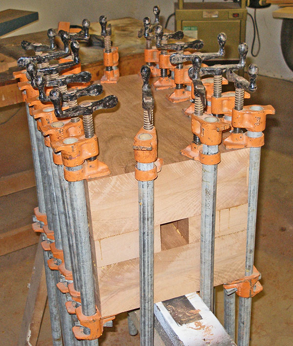
I had to make things square. This last glue-up is shown to the right. The top and bottom pairs are from the previous glue-ups, and these were glued to the middle pair. From this picture you can see how well the ends lined up. |
 |
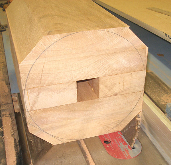
Knocking Down the Corners
After the glue-up, I knocked down the corners as much as I could with
the tablesaw. I drew the circle on the turning blank to make sure I
didn't cut too much. Obviously that wasn't anything I needed to worry
about afterall. This was the deepest I could cut, and it was no where
near deep enough to bring the corners down to a turning radius. |
 |
It Won't Turn Very Fast!
The sheer massiveness of the turning blank isn't really obvious until
you see it mounted on the lathe. Well now you know why I took the time
to install the VFD on the lathe! This lathe is one of the heaviest
tools in the shop, and the turning blank makes it look puny. |
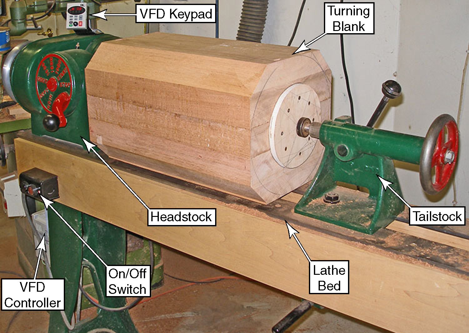 |
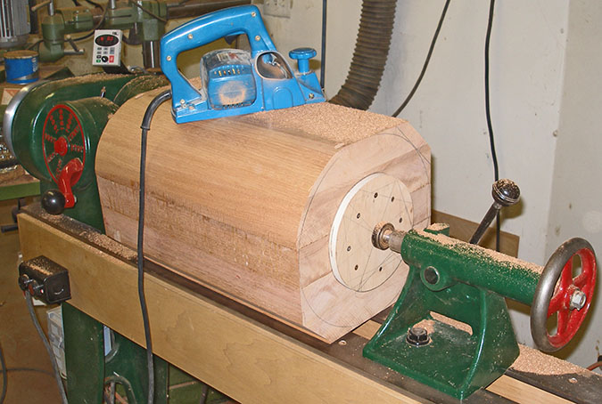
| Because the turning blank
almost touches the bed of the lathe, I needed to trim it nearly round
before I could rotate it. I used a powered hand planer to round the
corners. After rounding the first corner, I had to remove the blank
from the lathe just to rotate it to the next side. After rounding all four corners, it was time to spin the lathe. I discovered that the turning blank was so heavy that I had to reprogram the VFD for a higher starting torque just to get this spinning without stalling the motor. (I am glad I spent a few bucks more to get the programmable VFD.) Needless to say, I kept the speed pretty low until I was sure the blank was reasonably balanced. |
 |
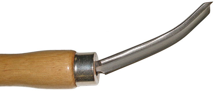
My Roughing Gouge Can Go Around CornersShortly after turning on the lathe, I realized that I could not get the banjo to fit between the blank and the lathe bed. (The banjo is shown in the next image below.) So I decided to use a makeshift tool rest clamped to the front of the lathe bed. The concept was good, but I was too impatient and mounted the tool rest too far away from the turning. I hadn't gotten very far before the gouge caught in the turning.Needless to say, it was a bit of an eye-opener, and it had me on edge for the whole rest of the turning. (Just in case you didn't know, that tool is supposed to be straight.) |
 |
|
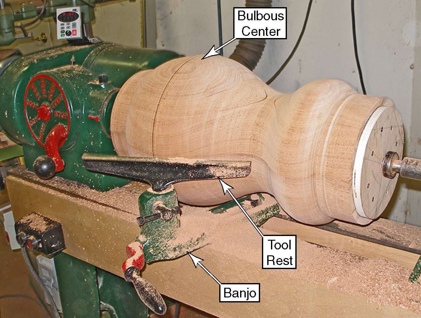
After my failed attempt at making an outrigger tool rest I decided to work inward from the ends until I can get the banjo under it. This idea was going well for the tailstock-end of the turning, but then I realized I didn't even have enough clearance at the headstock (between the headstock and the turning) to install the banjo at all. The only way I could begin turning at the headstock end was to retry the idea of a freestanding tool rest. This time I used the frame from a roller stand as a tool rest and braced it with wood to make it rigid, yet movable to keep it close to the turning. I Very Carefully roughed out the headstock end enough to get the banjo underneath. Even with the ends turned down, the center was still too thick to move the banjo from side to side, so I had to remove it from the lathe whenever I wanted to switch to the other end of the turning. I had the original column design created in SolidWorks and created a dimensional drawing from the model to show me the major diameters and where to place them. Unfortunately, I discovered that I don't have a caliper large enough to mark these diameters. So instead, it took longer, but I shaped the profile by eye. In the end, this was better because I was able to balance the curves on-the-fly for a more aesthetic shape. |
 |
|
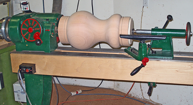
From the basic shape, I did some reshaping
for aesthetics
and then finished the two ends (top and bottom). Even the final turning
was still a little hairy because the only tool rest I own is the 12"
straight one,
and several areas of the profile forced me to have the gap between the
tool
rest and turning larger than desired. Memories of my bent gouge flashed
through my eyes more than a few times, and having a tool catch at this
point would
have been catastrophic. |
 |
| <<PREVIOUS NEXT>> |
 |