| I received the first pieces
of the machined hardware this week, and as much as I wanted to begin
mounting the core pieces into the main substrate of the table, I
decided to resume working on the pedestal of the table this weekend.
The main reason was to get these pieces out of the way so I had enough
room to work on the substrate disk later on. I also wanted to have the
welded steel subframe sitting on the actual pedestal before I began
mounting any hardware. The welded frame prevents the outer edges of the
table from sagging, so this will be critical for aligning components as
I begin construction. This frame is scheduled to be delivered later
next week. |
|
| I tossed around a lot of
ideas for mounting the columns to the pedestal base. The method needed
to prevent the columns from rotating, hold the columns firm for a
lifetime, and be at little risk for splitting the smaller columns. I
wanted to use threaded inserts so I could install or remove the columns
without weakening the threads. However, the fine outer threads of the
inserts just slice the wood fibers and have no holding power in
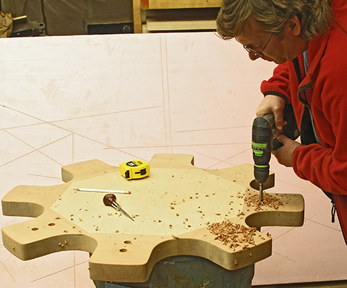
endgrain. So instead, I decided to use large (4-inch) lag screws to secure the columns. I used the extreme length so I could keep the pilot hole large yet still provide good holding power. The first step was to countersink for the hex heads with a forstner bit. The holes were laid out radially so they would not lie in the same plane as the grain of the base pieces. When ever you use a forstner bit as a countersink, you need to bore the outer hole before drilling the clearance hole for the screw shank. |
 |
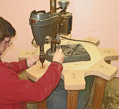
| Before I had bandsawed the
scalloped edges of the base, I had marked and drilled small pilot holes
in the base at the center of each column. I temporarily secured each
column with a single construction screw. The dimple from the lathe’s
live center ensured the screw was centered in the column. With the forstner bores completed, I setup a benchtop drillpress on the base so I could drill the pilot holes plumb. I drilled through the base and into the columns as deep as possible. The same process was used for the center column too. The reason why the base is sitting over an empty garbage can is because the center column is hanging down in the middle. As I removed each column, I labeled them according to position and orientation so they could be reinstalled later the same way they were drilled. Then I re-drilled the holes in the base for clearance for the screw shanks.
|
 |
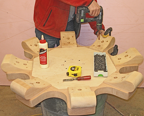
| Drilling all of the holes in the
eight feet was very tedious. First, two clearance holes were drilled so
I could get a socket driver through to drive the lag screws. These were
drilled from the curved side down, so piloting the forstner bit was a
slow and challenging process for each bore. Next I countersunk the mounting holes for the feet. Each of these was stopped 3/4 inch short of penetrating the foot. Then clearance holes were drilled in the center of the countersinks. To secure the feet, a clamp was used to hold the piece fast as the screws were started. The feet were glued and screwed to the base. |
 |
| For a better finish, I lacquered
the base before installing the columns. I used one coat of sanding
sealer and two coats of pre-catalyzed topcoat. Yes, even though the
installers will ever see the underside of the pedestal, it still has a
full finish. |
 |
| Each column was lacquered
separately. I use an airless sprayer for a high-build finish. I love
this part because this is where I get to see the grain come to life. |
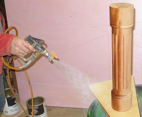 |
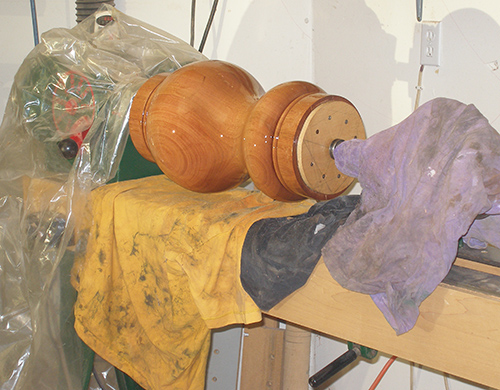
| At first I sprayed the center
column the same way I sprayed the smaller columns, but I realized I
couldn’t get a consistent cover across the extreme variations of the
shape. So I covered the lathe with plastic and old rags to protect it
from overspray, and remounted the column on the lathe. (Remember when I
said earlier that I didn’t want to remove the plywood cap just in case
I needed to remount it on the lathe?) I set the VFD to about 100 rpm and started to spray. Spraying habits die hard, and I had a hard time forcing myself not to sweep the sprayer across the column like I would with a static object. Even then, I had a hard time forcing myself not to use short trigger bursts. Initially, my bursts were so short that I wasn’t even getting a full revolution out of the column. Once I got past this engrained training, I was able to lay down a very high-build finish without fear of runs. What is surprising is that if I had laid down this thick of a finish on a horizontal surface, it would have off-gassed and resulted in fisheye. The other thing I was concerned about was that the windage from the spinning column would cause the lacquer to skin over before it leveled. Contrary to my initial concerns, I was absolutely amazed at how well the finish leveled and remained fluid. After spinning for a few minutes at 100 rpm, I dropped the lathe speed to 40-60 rpm for about 10 to 15 minutes until I was sure it would not sag. I applied two coats while the column was on the lathe (plus the original vertical coat). As you can see in the next picture, the resulting finish is incredibly smooth. I’ve done this for wipe-on finishes, but never for a high-build lacquer finish. I took a risk, and it really paid off. |
 |
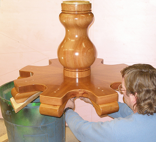
| After letting all of the
components dry for an hour or so, I started assembling the columns. In
order to install the center column, I spanned the base between a
garbage can and a shop stool. (As you can see, I use these cans for a
lot of spraying.) Because of my pre-assembly steps, I knew I could still pick up and handle the base while the center column was installed, so having the piece so far off the ground was not a problem. The benefits of the way I made the original glue-up on the center column are really becoming evident with the finish in place. |
 |
| To install the outer columns, I
lowered the base down to a 5-gallon bucket. This made installation more
difficult, but I knew than getting the finished pedestal down onto the
ground with all of the columns installed was not going to be easy. |
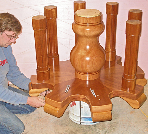 |
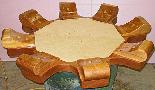
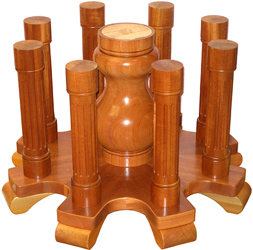
| After the columns were
installed, I slid the pedestal off the can and onto a sheet of
cardboard. However, after seeing the photograph, I realized that the
color of the cardboard blended too much into the wood, so I stripped
out the background to get this image. Oh, I finally removed the plywood center from the middle column, although the absence of lacquer makes this hard to see. After the welded steel frame arrives, I need to cut a cap for the pedestal that fits the frame, and then secure this cap to the pedestal. When the table is installed at its final location, the installers will bolt the welded frame to this plywood cap. |
 |
Up Next: Prepping the substrate for initial hardware. |
|
| <<PREVIOUS NEXT>> |
 |